Visualizing motion with marker particles
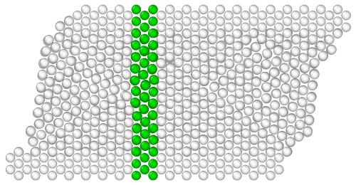
This step-by-step tutorial will guide you through creating an animation from an MD simulation of a simple shearing experiment, as shown on the right. You will learn how to highlight a specific group of atoms - initially located in a narrow region - using marker colors to visualize atomic motion within the crystal throughout the simulation.
You will learn about the Freeze Property modifier in OVITO, which helps preserve the initial particle selection set from the first frame of the trajectory.
Step 1: Load simulation trajectory
Start by downloading the simulation trajectory file
shear.dump to your computer. This file was generated by the shear simulation script found in the LAMMPS examples folder. Use the function
to open the file shear.dump in OVITO.
Step 2: Adjust animation speed
The simulation trajectory consists of 41 frames, as indicated in the timeline below the viewports of OVITO.
Drag the time slider with the mouse to manually navigate through frames.
Press the Play
button in the animation toolbar to loop the animation in the interactive viewports.
To adjust the animation speed:
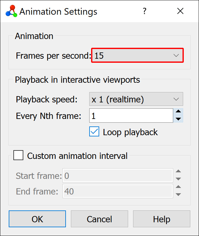
Open the Animation settings dialog
.
Set Frames per second to 15.
This setting affects both interactive playback and the frame rate of exported movie files.
Step 3: Create particle selection
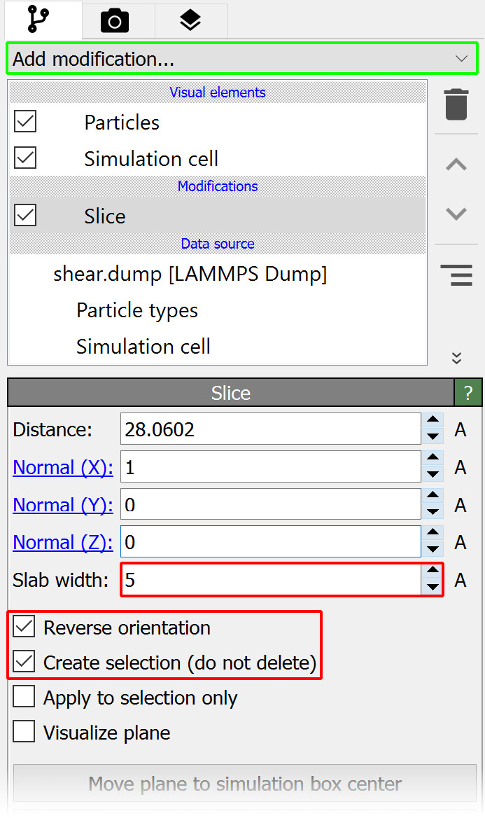
Next, insert the Slice modifier into the data pipeline to select all particles within a narrow slab of the crystal:
Select Slice from the Add modification… list (Modifications section).
The modifier will now appear as a new item in the pipeline editor.
By default, the Slice modifier removes particles on one side of the slicing plane. However, in this case, we want to select particles instead of deleting them. In the Slice modifier panel:
Enable Create selection (do not delete).
Set Slab width to 5 angstroms.
Check Reverse orientation to select particles located between the two parallel planes.
Step 4: Color the marker particles
OVITO highlights selected particles in bright red in the viewports, but this color is only a temporary indicator to show the selection state. To permanently change the particle color for rendering:
Select Assign color from the Add modification… drop-down list (Coloring section).
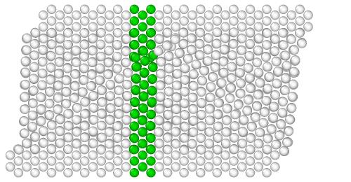
Choose green as the new color for the selected particles.
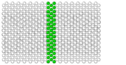
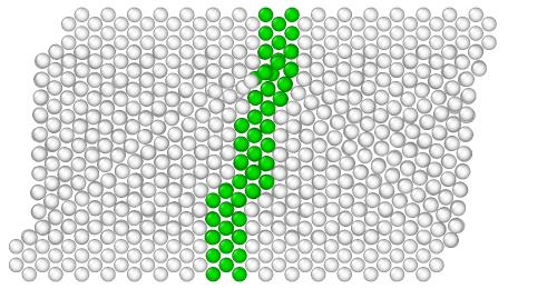
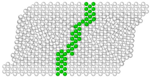
Here is what the result looks like at different frames of the simulation:

Step 5: Freeze the particle colors
If you play the animation now, you will notice that the particle selection is not static. The green slab remains straight, but different particles turn green as they enter the selection region, while others revert to white when leaving.
This happens because the Slice and Assign Color modifiers are applied dynamically in each frame. OVITO automatically recalculates the selection and colors whenever particles move.
Freezing the selection
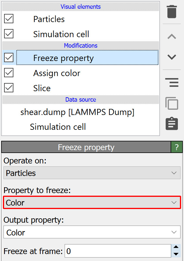
To ensure the same set of particles remains green throughout the animation, we need to “freeze” their color state. Freezing a particle property means transferring the property values from the first frame of the trajectory to all other frames. To freeze the particle colors:
Add the Freeze Property modifier to the pipeline.
Set Property to freeze to Color.
This locks each particle’s color from frame 0 and applies them consistently throughout the animation:
Note
We have placed the Freeze Property modifier at the top of the modifier stack, which means it will be executed last - after the two other modifiers. This ordering is important: The Freeze Property modifier is only able to preserve the particle state produced so far by preceding modifiers. Any effects of downstream modifiers in the pipeline would not be visible to the Freeze Property modifier.
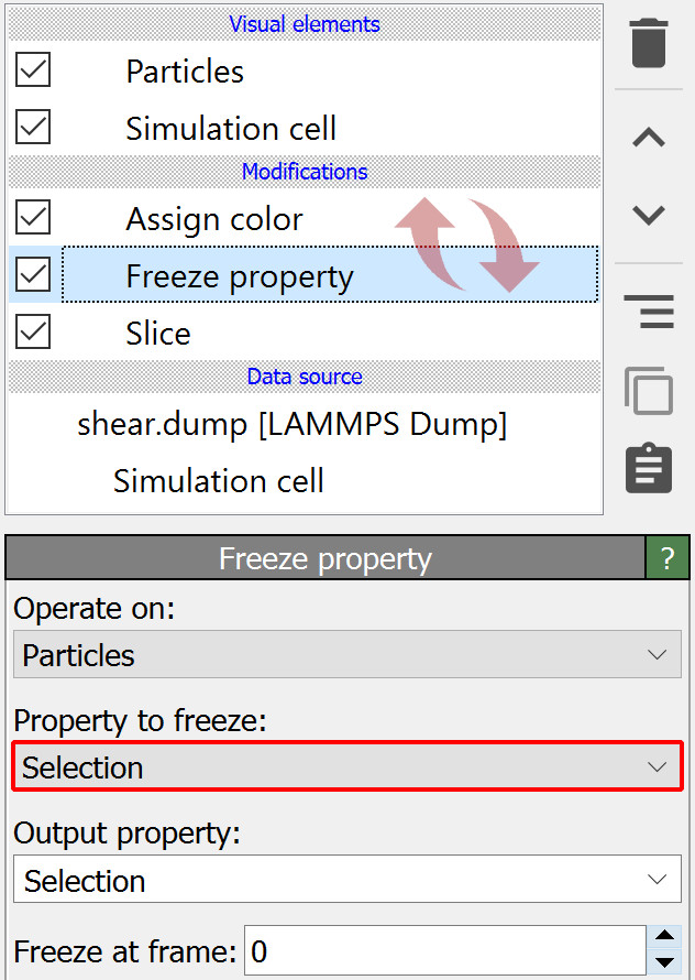
Freezing the selection instead of the colors
Instead of freezing the particle colors, you can freeze their selection state:
Move the Freeze Property modifier before (below) the Assign color modifier in the stack.
Set Property to freeze to Selection.
Now, the frozen selection from frame 0 remains unchanged, and the Assign color modifier applies the green color to the same selected particles in every frame.
Step 6: Render a movie
To complete this tutorial you will now render a movie of the simulation and save it as a video file.
Switch to the Render tab of the command panel and set the rendering range to Complete animation.
Click Choose… and specify the name and format of the video file to be written by OVITO, e.g. shear_marker.mp4.
The option Save to file should now automatically be turned on.

Make sure the Top viewport is currently active. If there is no Top viewport, switch the current viewport to top view using the viewport menu. A Top viewport shows the current scene from above, along the negative z-axis, using a parallel projection.
Finally, press the button Render active viewport to start the rendering process.
Tip
To further refine the visualization you may want to perform a few additional steps:
Turn off the display of the Simulation cell visual element in the pipeline editor.
Adjust the display radius of the particles in the Particles visual element to a value of 1.0.
Activate in the viewport menu to check the visible viewport region before rendering the video.
Download the tutorial solution
If you’d like to skip ahead or verify your solution, download the preconfigured OVITO session state file: shear.ovito
Save it in the same folder as the trajectory file shear.dump. Open it using .
If you encounter any issues, feel free to contact us at support@ovito.org to help us improve this tutorial.