VisRTX renderer pro
Added in version 3.10.0.
VisRTX is a scientific visualization renderer based on the NVIDIA OptiX™ Ray Tracing Engine. It offers hardware-accelerated ray-tracing and can generate high-fidelity scene renderings including global illumination effects and shadows. Compared to CPU-based ray-tracing engines like Tachyon or OSPRay, this renderer can achieve near real-time performance on modern GPU hardware.
VisRTX requires NVIDIA hardware with CUDA support and a current NVIDIA graphics driver (CUDA 12.6+). The renderer is not available on the macOS platform and doesn’t work on Windows Subsystem for Linux (WSL), because this environment lacks the NVIDIA OptiX™ driver components required by VisRTX.
Caution
VisRTX is still under active development by the HPC Visualization Developer Technology team at NVIDIA in close cooperation with the OVITO developers, who integrate the technology. For more information, visit https://github.com/NVIDIA/VisRTX. Please report any issues you encounter to the OVITO developers. Missing features and capabilities:
Meshes with per-vertex transparency values
Meshes with highlighted edges (wireframes)
Materials with adjustable specular reflection parameters
Flat-shaded primitives
Note
On first use of the VisRTX renderer, it will compile RTX shader programs for your GPU architecture. This process can take up to several minutes, but happens only once. The compiled shader programs get cached on disk and are reused in subsequent OVITO sessions.
Tip
The VisRTX renderer can also be used in the interactive viewports of OVITO to visualize the scene in real-time with high-quality ray-tracing effects. To enable the VisRTX renderer in the viewports, open the viewport graphics configuration dialog and select the “NVIDIA VisRTX” renderer.
Parameters
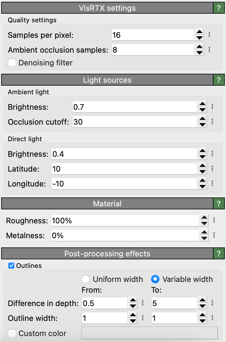
Quality settings
- Samples per pixel
The number of ray-tracing samples computed per pixel of the output image (default value: 16). Larger values can help reduce aliasing artifacts.
- Ambient occlusion samples
The number of samples used to compute ambient occlusion effects (default value: 8). Larger values can help to reduce visual artifacts.
- Denoising filter
Applies a denoising filter to the rendered image to reduce noise inherent to ray-traced images (default value: on).
Depth of field
When depth-of-field rendering is active, only objects located exactly at the distance from the camera specified by the focal length will appear sharp. Objects closer to or farther from the camera will appear blurred. To focus on a specific object, use the Pick in viewport button and click on the desired object in the viewport to be rendered. The focal length parameter will be automatically adjusted so that the picked location is in focus.
The aperture radius controls how blurred out-of-focus objects will appear (default: 0.5).
Note that the focal blur effect requires a perspective projection; it does not work in viewports using a parallel projection.
Ambient light
- Brightness
Radiance of the ambient light source (default value: 0.7).
- Occlusion cutoff
Maximum range of the ambient occlusion (AO) calculation (default value: 30.0). More distant objects beyond this cutoff range (given in simulation units) will not contribute to the computed local light occlusion effect. Decreasing this parameter will typically brighten up the inside of dark cavities that are otherwise fully occluded by the surrounding objects. Increasing it will make the AO effect stronger and lead to darker contrast.
Short AO cutoff range
Long AO cutoff range
Direct light
- Latitude & Longitude
Latitude (north-south) and longitude (east-west) position of the direct light source relative to the camera (default values: 10.0° and -10.0°). Upon rotation of the viewport camera, this light source will move with the camera, maintaining a constant relative light direction. A value of 0.0° places the light source in line with the camera’s viewing direction. Input is expected in degrees. The valid parameter range is [-90°, +90°] for latitude and [-180°, +180°] for longitude.
- Brightness
Irradiance of the direct light source (default value: 0.5).
Material
VisRTX supports two material types: Standard and Physically-Based. The standard material is faster, making it ideal for real-time interactive workflows. The physically-based model provides additional parameters for tuning the look of rendered objects.
The material settings are applied globally to all scene objects.
Standard material
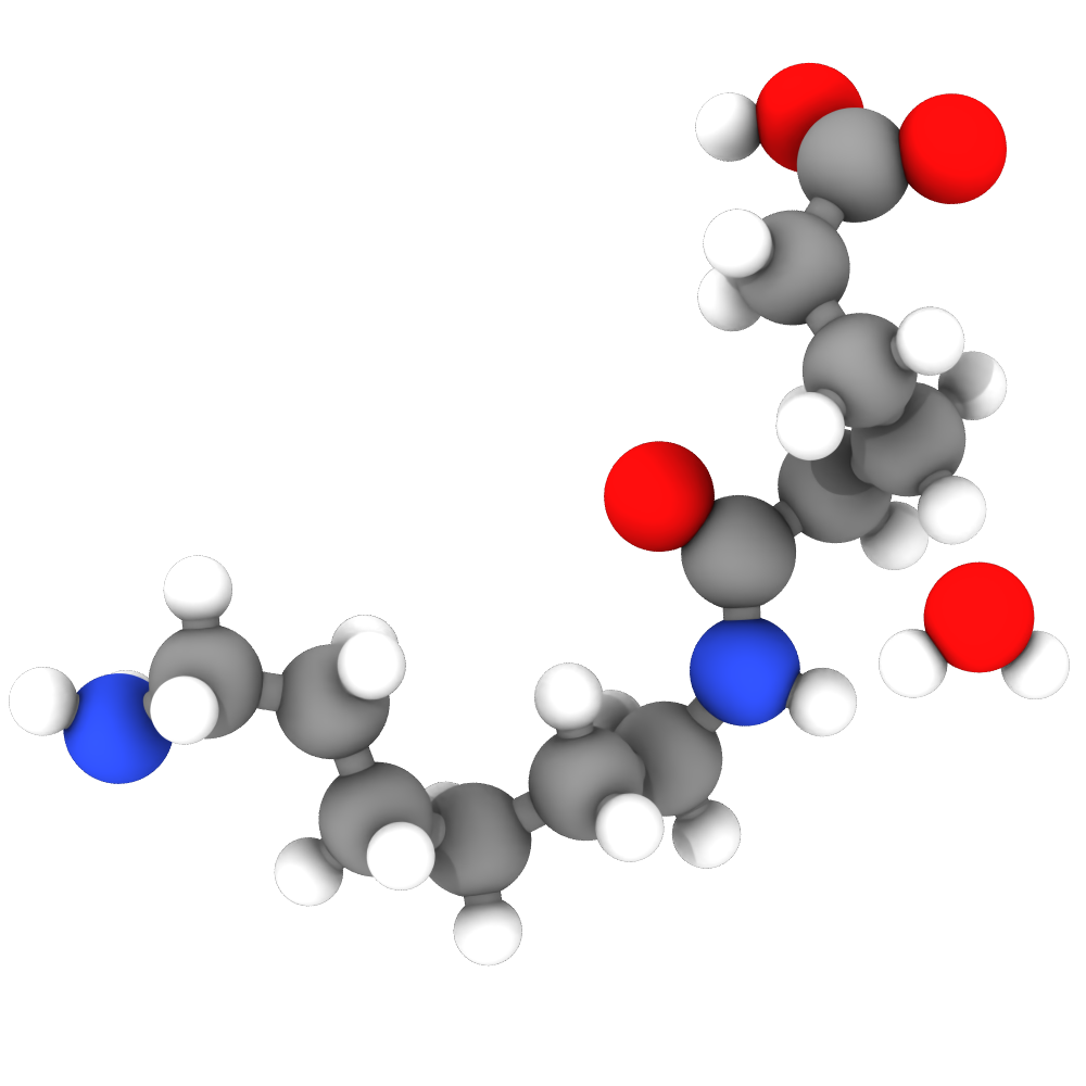
Standard material
The Standard material corresponds to the matte material from the ANARI specification, which reflects light uniformly into the hemisphere. It is suitable for most purposes and is the current default choice in OVITO Pro.
Physically-based material
This material model behaves similar to glTF’s pbrMetallicRoughness material and consists of a mixture of a metallic and a dielectric/diffuse component. The ratio between both contributions is determined by the Metalness parameter.
- Roughness
Controls the variation of microfacets and thus how polished the metal will look (default value: 45%). A value of 0% gives a perfectly polished mirror surface, while a value of 100% gives a completely matte surface.
- Metalness
A value in the range 0-100% controlling the mixture of dielectric/diffuse and metallic model contributions (default value: 40%).
|
|
|
|---|---|---|
Roughness: 20% |
Roughness: 45% |
Roughness: 60% |
Metalness: 0% |
Metalness: 40% |
Metalness: 100% |


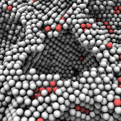
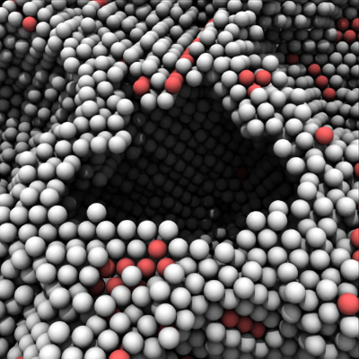
Post-processing effects
- Outlines
Enables the drawing of outlines along object edges. The outlines are depth-aware, meaning that they are only drawn when the depth difference between two overlapping objects exceeds a certain threshold. Optionally, the width of the outlines can be adjusted based on the depth difference, which can help to improve visibility of outlines in complex scenes.

Outlines in the interactive viewport.

Outlines in the rendered image.
- Depth Difference & Outline Width
- Uniform Width Mode
In this mode, a single value is used for both the depth difference and the outline width. An outline with a constant width is drawn around all objects that have a depth difference greater than the specified value relative to the background.
- Variable Width Mode
In this mode, the outline width increases linearly from the minimum to the maximum width as the depth difference between overlapping objects varies from the minimum to the maximum depth difference. When switching from Uniform Width Mode to Variable Width Mode, any missing values for depth or line width will be automatically set to their default values.
- Custom Color
When disabled, the outline color is automatically determined based on the background color: white outlines for dark backgrounds and black outlines for light backgrounds. When enabled, the manually selected color is used instead.
See also
AnariRenderer (Python API)