Affine transformation
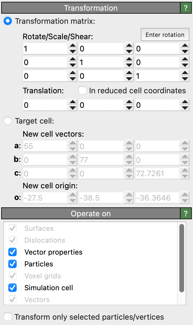
This modifier applies an affine transformation to the system or specific parts of it. It may be used to translate, scale, rotate or shear the particles, the simulation cell and/or other elements. The transformation can either be specified explicitly in terms of a 3-by-3 matrix plus a translation vector, or implicitly by prescribing a constant target shape for the simulation cell.
Given a 3-by-3 linear transformation matrix \(\mathbf{M}\) and a translation vector \(\mathbf{t}\), which together describe a general affine transformation, the transformed position of a particle at the original Cartesian position \(\mathbf{x}\) is computed as \(\mathbf{x}' = \mathbf{M} \cdot \mathbf{x} + \mathbf{t}\). This notation uses column vectors.
The button Enter rotation opens a dialog box which lets you specify a 3D rotation axis, a rotation angle and a center of rotation. Based on these inputs, OVITO computes the corresponding affine transformation for you.
Translation in reduced coordinates
The option In reduced cell coordinates changes the affine transformation method such that the translation vector \(\mathbf{t}\) is specified in reduced cell coordinates instead of Cartesian coordinates, i.e. in terms of the three vectors that span the simulation cell (after they have been transformed by the linear matrix \(\mathbf{M}\)).
In other words, activating this option changes the affine transformation equation to \(\mathbf{x}' = \mathbf{M} \cdot (\mathbf{x} + \mathbf{H} \cdot \mathbf{t})\) with \(\mathbf{H}\) being the 3-by-3 cell matrix formed by the three edge vectors of the original simulation cell.
Transform to target cell
In Target cell mode, the modifier dynamically computes the affine transformation to be applied to the system from the current shape of the simulation cell and the specified target shape. The contents of the simulation box (e.g. particles, surface meshes, etc.) will be mapped to the new cell shape accordingly, unless you turn off their transformation (see next section).
Tip
Use this option to replace a time-varying cell, e.g. from a constant-pressure simulation, with a constant cell shape of your choice.
Transformed elements
The option Transform only selected particles/vertices restricts the action of the modifier to the subset of currently selected particles or mesh and line vertices.
Furthermore, you can specify the object classes the modifier should touch:
Element type |
Description |
|---|---|
Applies the transformation to the origin of the simulation cell and the linear part to the three cell vectors. |
|
Applies the transformation to the coordinates of particles ( |
|
Applies the linear part \(\mathbf{M}\) of the affine transformation to vectorial properties, e.g. the particle properties |
|
Applies the transformation to the domain shape of voxel grids. |
|
Applies the transformation to the vertices of surface meshes. |
|
Applies the transformation to the vertices of triangle meshes. |
|
Applies the transformation to the vertices of line objects. |
|
Applies the transformation to the positions and directions of vector objects. |
|
Applies the transformation to dislocation lines and their Burgers vectors. |
If there are multiple objects of a class present in the modifier’s input, you can optionally restrict the modifier to a particular one of them. Otherwise, the modifier will process all objects of the enabled classes.
See also
ovito.modifiers.AffineTransformationModifier (Python API)